
Fig: Material balance diagram for top plate (a), total condenser (b) and partial condenser (c). source: Unit Operation of chemical engineering; W.L McCabe
Top Plate: Figure ‘a’ shows material balance diagram for top plate. The concentration of vapor from top plate is Y1 and that of reflux to the top plate is Xc. In accordance with general properties of operating lines, the upper terminus of the line is at the point (Xc, Y1).
Total condenser: The frequently used simplest arrangement for obtaining reflux and liquid product is Single total condenser as shown in figure ‘b’ which condenses all vapor from column and supplies both reflux and product. When such single total condenser is used, the concentration of vapor from top plate of the reflux and overhead product are equal and can all be denoted by XD. The operating terminus of the operating line becomes point (XD, YD) which is intersection of the operating line with diagonal.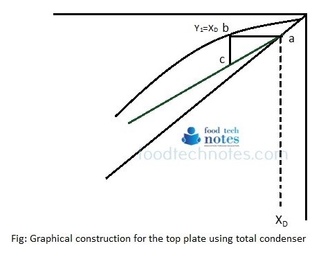 In total condenser, it is assumed that condenser removes latent heat only and that the condensate is liquid at its bubble point. Then the reflux L is equal to LC, the reflux from the condenser and V = V’. If the reflux is cooled below bubble point, a portion of vapor coming to plate 1 must condense to heat the reflux. Therefore, V’< V and L> LC. The additional amount of ∆L that is condensed inside column is found from equation
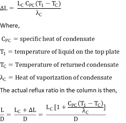
Temperature T1 is not usually known, but it normally almost equal Tbc, the bubble point temperature of the condensate. Thus Tbc is commonly used in place of T1 in above equation.
Partial condenser: In partial condenser, the vapor is only partially liquefied. The liquid produced is returned to the column as liquid and vapor product stream is removed. When partial condenser or dephlegmator is used, liquid reflux doesn’t have same composition as overhead product. I.e. XC ≠ XD.
Sometimes two condensers are used in series, first a partial condenser to provide reflux then final condenser to provide liquid product. Such arrangement is shown in figure ‘c’. Vapor leaving the partial condenser has composition Y’ which is same as XD. Under this condition, following diagram applies.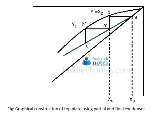 The operating line passes through the point (XD, XD) on the diagonal but as far as column is concerned, the operating line ends at point a’ which has coordinates (XC, Y1). Here, ∆ a’b’c’ represents top plate in the column and ∆ aba’ represents additional theoretical stage in distillation column.
About Author

Name : Pratiksha Shrestha
pratiksha.shrestha2001@gmail.com
Ms. Shrestha holds masters degree in food engineering and bioprocess technology from Asian Institute of Technology (AIT) Thailand. She is currently working for Government of Nepal at Department of Food Technology and Quality Control (DFTQC), Kathmandu. She is also a teaching faculty in College of Applied food and Dairy Technology (CAFODAT) affiliated to Purbanchal university, Nepal.